top of page

FairWinds Manufacturing produces most of our parts in Jackson Center, PA , while carefully sourcing select castings globally to ensure top quality and cost efficiency.

Hendrix Coupler - Series 2

  • photo coming soon

    Cylinder

    Quanity: 1

    When calling about a Series 2 Cylinders.
    Please make sure to have this measurments. 

    Rod Diameter: 

  • photo coming soon

    Lever

    Quanity: 1

  • photo coming soon

    Lever Cylinder Pin

    Quanity: 1

  • photo coming soon

    Weld-on Pin Support

    Quanity: 2

  • photo coming soon

    Front Lever Cylinder Pin Retaining Ring

    Quanity: 2

  • photo coming soon

    Comer Support Brace

    Quanity: 2

  • photo coming soon

    Lever Stop Block

    Quanity: 1

  • photo coming soon

    Cast Back Plate

    Quanity: 1

  • photo coming soon

    "C" Boss

    Quanity: 1

  • photo coming soon

    Hook Plate

    Quanity: 2

  • photo coming soon

    Lever Stop Pin

    Quanity: 1

  • photo coming soon

    Front Lever Pin Retaining Ring

    Quanity: 2

  • photo coming soon

    Front Lever Boss

    Quanity: 2

  • photo coming soon

    Front Brace

    Quanity: 1

  • photo coming soon

    Mechanical Lock Pin

    Quanity: 1

  • photo coming soon

    Front Lever Pin

    Quanity: 1

  • photo coming soon

    Front Lever Casting

    Quanity: 1

  • photo coming soon

    Front Lever Cylinder Pin

    Quanity: 1

Top Section

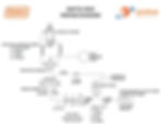
Hendrix-Series2-Bottom-CouplerDiagram
Hendrix Coupler Series 2 Diagram
  • photo coming soon

    Stick Retaining Boss

    Quanity: 1

  • photo coming soon

    Link Retaining Boss

    Quanity: 1

  • photo coming soon

    Stick Spacing Boss

    Quanity: 1

  • photo coming soon

    Link Spacing Boss

    Quanity: 1

  • photo coming soon

    Attachment Pin, Stick

    Quanity: 1

  • photo coming soon

    Attachment Pin, Link

    Quanity: 1

  • photo coming soon

    Attachment Pin Retaining Bolt

    Quanity: 2

  • photo coming soon

    Attachment Pin Retaining Nut

    Quanity: 4

  • photo coming soon

    Lever Pin

    Quanity: 1

  • photo coming soon

    Ear Plate

    Quanity: 2

  • photo coming soon

    Spacer Plate

    Quanity: 2

  • photo coming soon

    Lever Boss Retaining Ring

    Quanity: 2

  • photo coming soon

    Lever Boss

    Quanity: 2

  • photo coming soon

    Hook Plate Shim

    Quanity: 2

Bottom Section

Bottom Section

Hendrix-Series2-Bottom-CouplerDiagram
  • photo coming soon

    Cylinder

    Quanity: 1

    When calling about a Series 2 Cylinders.
    Please make sure to have this measurments. 

    Rod Diameter: 

  • photo coming soon

    Lever

    Quanity: 1

  • photo coming soon

    Lever Cylinder Pin

    Quanity: 1

  • photo coming soon

    Weld-on Pin Support

    Quanity: 2

  • photo coming soon

    Front Lever Cylinder Pin Retaining Ring

    Quanity: 2

  • photo coming soon

    Comer Support Brace

    Quanity: 2

  • photo coming soon

    Lever Stop Block

    Quanity: 1

  • photo coming soon

    Cast Back Plate

    Quanity: 1

  • photo coming soon

    "C" Boss

    Quanity: 1

  • photo coming soon

    Hook Plate

    Quanity: 2

  • photo coming soon

    Lever Stop Pin

    Quanity: 1

  • photo coming soon

    Front Lever Pin Retaining Ring

    Quanity: 2

  • photo coming soon

    Front Lever Boss

    Quanity: 2

  • photo coming soon

    Front Brace

    Quanity: 1

  • photo coming soon

    Mechanical Lock Pin

    Quanity: 1

  • photo coming soon

    Front Lever Pin

    Quanity: 1

  • photo coming soon

    Front Lever Casting

    Quanity: 1

  • photo coming soon

    Front Lever Cylinder Pin

    Quanity: 1

How To

Cylinder Identification Worksheet.png

- Measure the diameter of the Chrome Rod Size. 

- Measure Diameter Mounting Holes 

Switch Box.JPG

Follow the diagram to wire your switch box

bottom of page